Development of a 1/10 Scale Ackermann Steering Robot with Autonomous Navigation Using ROS 2 and Nav2

1. Introduction
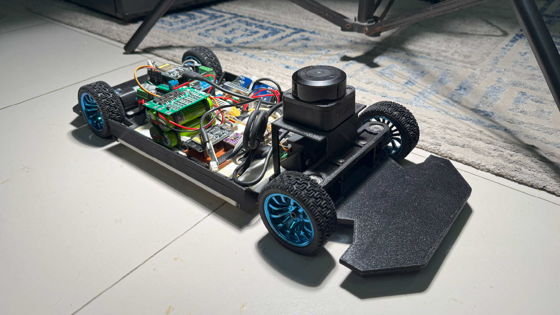
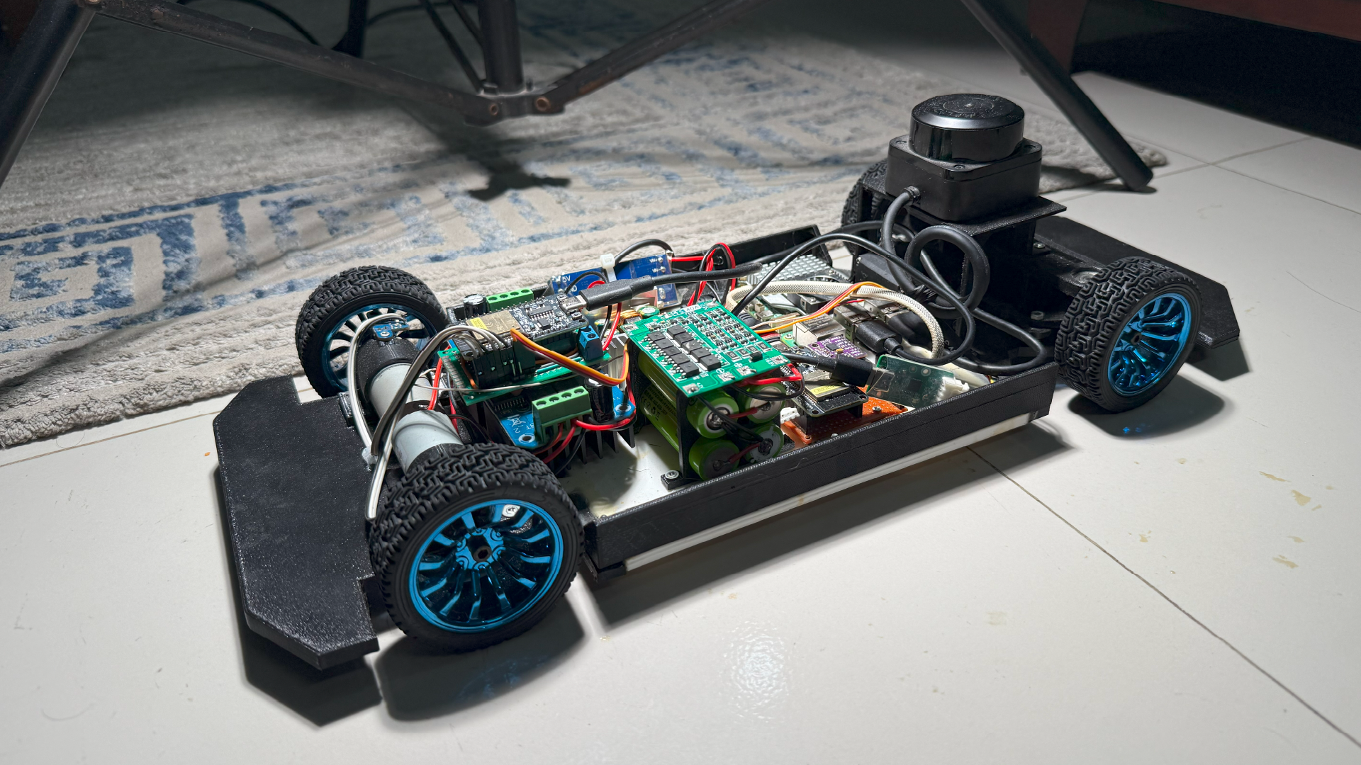
This project presents the design and implementation of a fully autonomous 1/10 scale Ackermann steering ground vehicle, developed entirely from the ground up. Unlike previous attempts, this iteration emphasizes precision and reliability, with every mechanical component — including the steering system, drivetrain, and sensor mounts — meticulously designed and 3D printed for high dimensional accuracy.
The objective was to build a robust platform capable of performing full-stack autonomous navigation using the ROS 2 ecosystem, with support for SLAM, real-time localization, and path planning via the Nav2 stack. The system integrates a custom electronics suite, including an ESP32-based control board, high-resolution encoders, inertial sensors, and a 2D LiDAR for obstacle detection and mapping.
From CAD modeling and mechanical fabrication to embedded system design and ROS 2 software development, this project showcases a holistic engineering approach to autonomous vehicle development at a small scale — ideal for research, prototyping, and education.
2. Mechanical Design
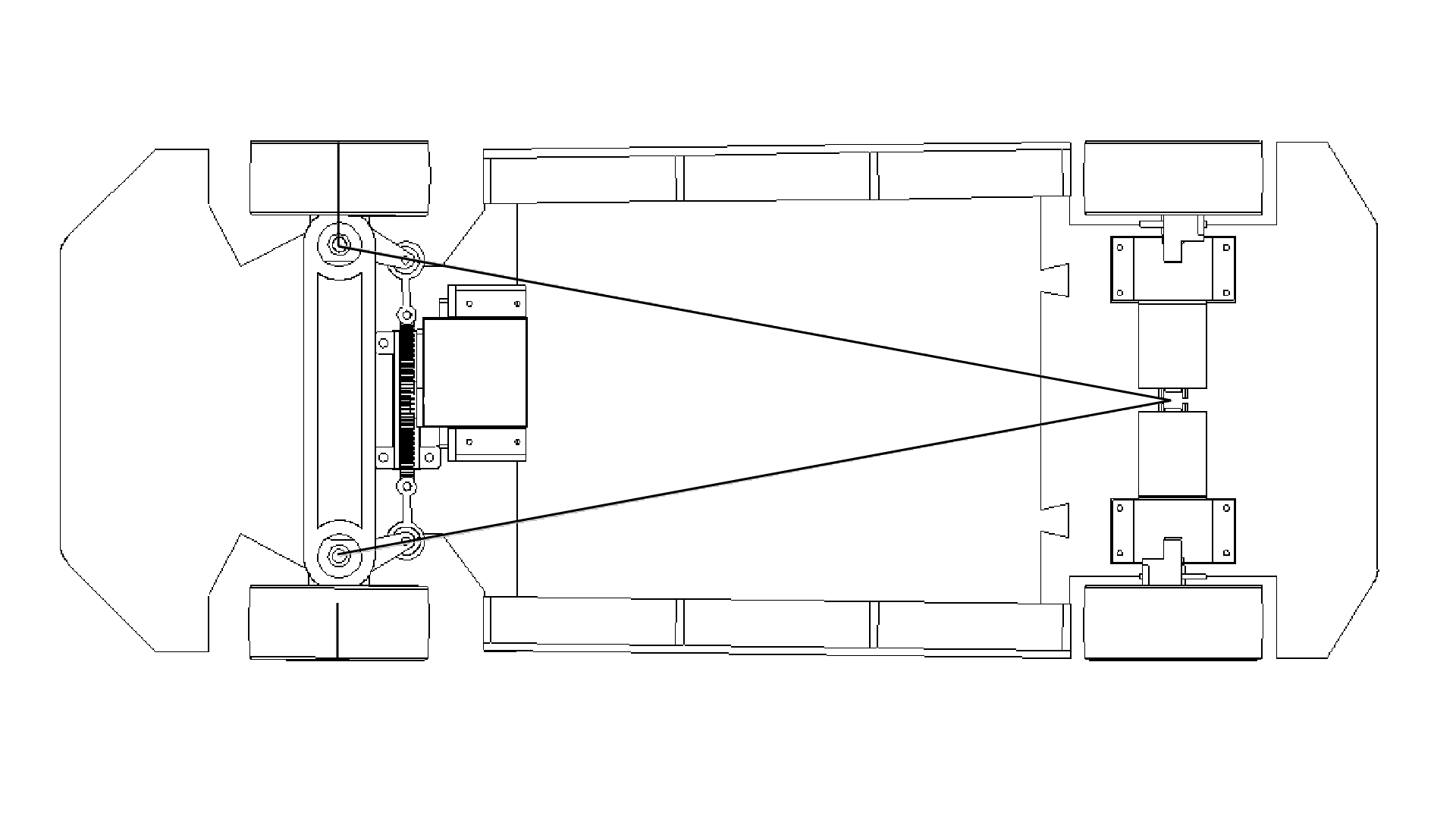
All mechanical components of the autonomous Ackermann vehicle were custom-designed in SolidWorks and fabricated using high-precision 3D printing. The design was modular, split into three major subassemblies: Steering Mechanism, Drive Motor Assembly, and Chassis, each optimized for performance, durability, and ease of integration with electronics and sensors.
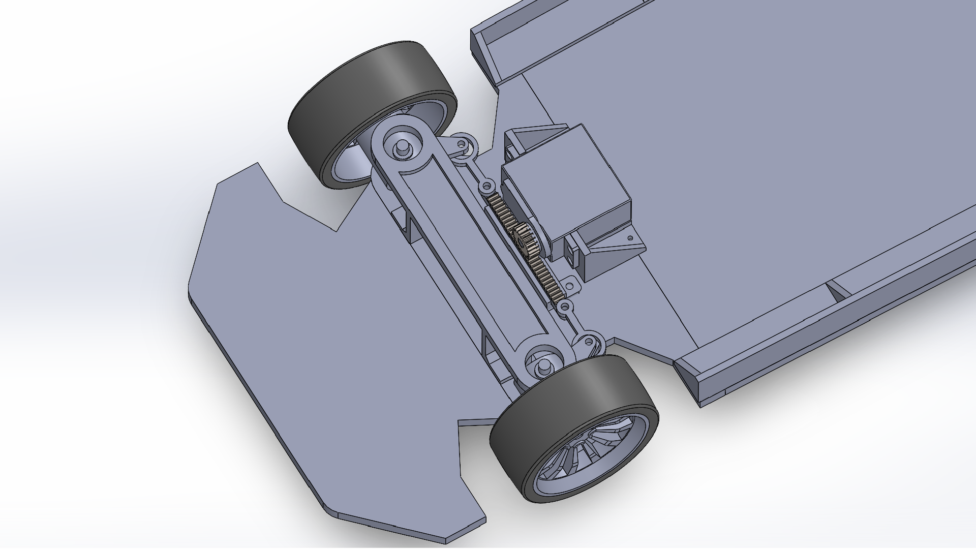
2.1 Steering Mechanism
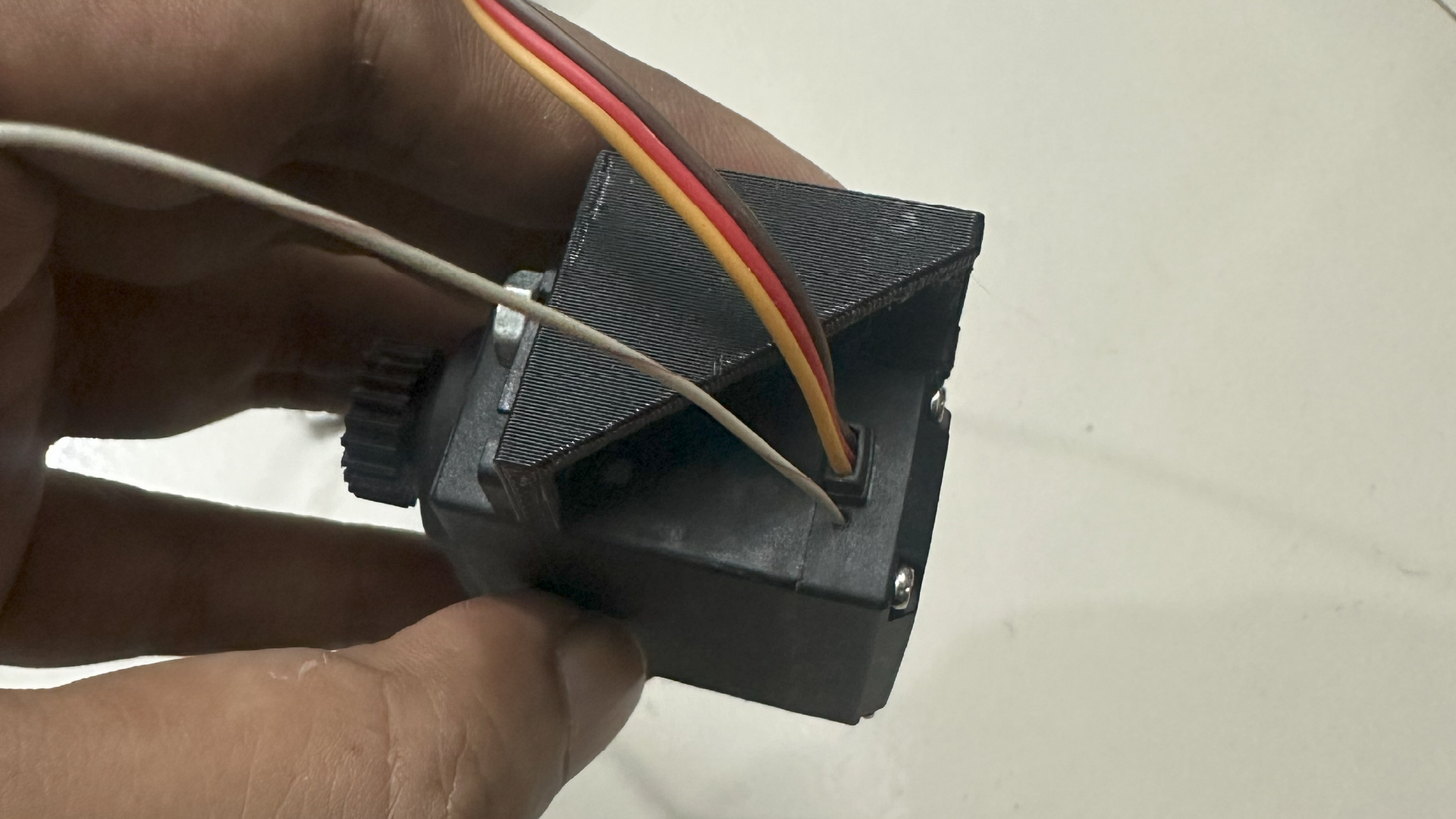
The steering system was built to conform with Ackermann geometry, ensuring accurate wheel alignment during turns to reduce lateral slip. A rack-and-pinion mechanism was driven by a high-torque digital servo motor for precise control.
Key features:
- Double-bearing support in the steering uprights to eliminate wheel wobble and ensure consistent steering response.
- Custom 3D-printed upright knuckles with integrated mounting points for wheels and linkages.
- Servo-actuated rack with minimal backlash for accurate input-output translation.
This design provided a mechanically reliable base for odometry and motion control.

3. Electronics Design and PCB Integration
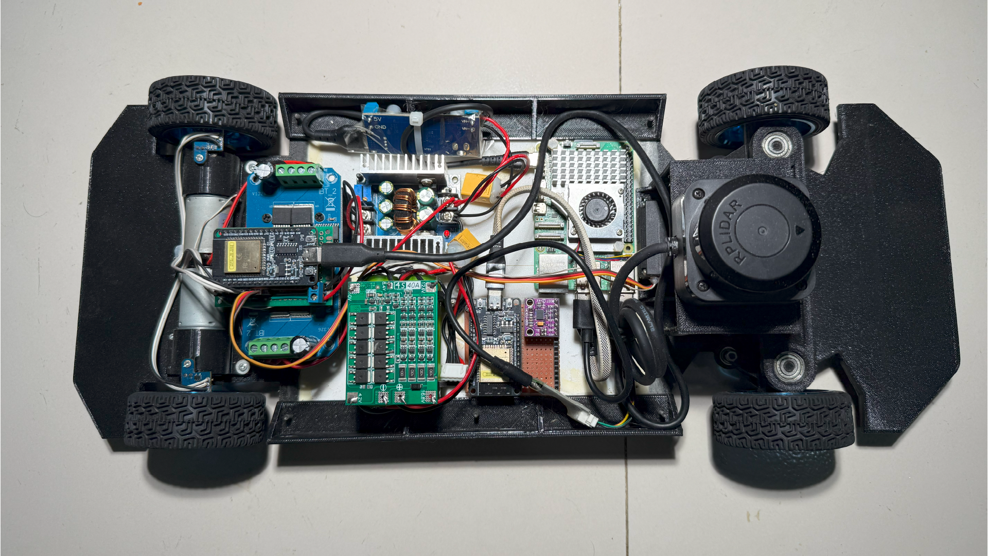
To support real-time sensor processing and low-level actuation with minimal latency, this system uses a dual-ESP32 architecture, each hosted on a custom-designed PCB. This separation ensures dedicated processing for both motion control and state estimation, while also improving signal integrity and cable management through compact, soldered connections.
Each PCB was designed for robustness, modularity, and ease of integration with the mechanical chassis — significantly reducing wire clutter and improving long-term reliability in an actively navigating robot.
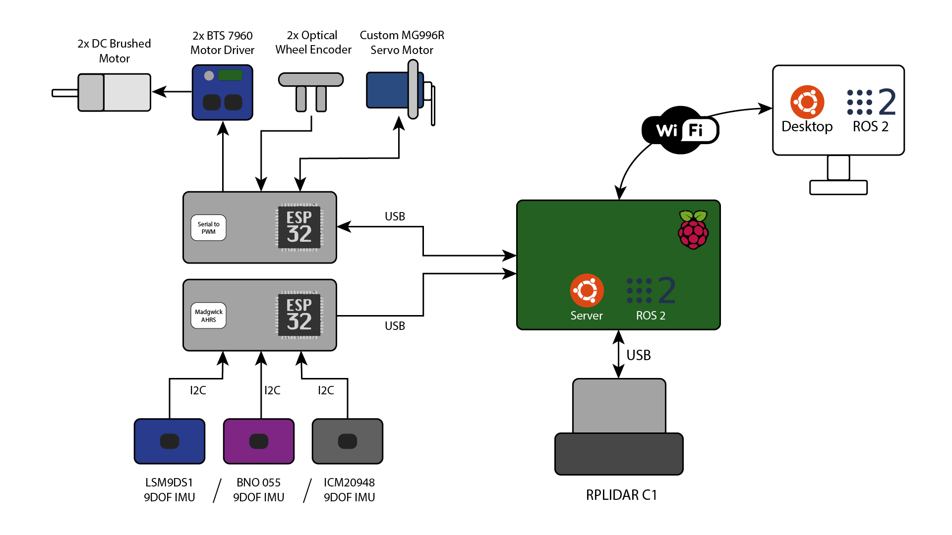
3.1 Dual-ESP32 Architecture
To offload tasks and minimize timing bottlenecks, the platform uses two ESP32 microcontrollers:
- ESP32-MCU 1 (Drive and Steering Control)
- Reads quadrature encoders from both rear wheels.
- Drives two DC motors using BTS7960 motor drivers.
- Controls the MG996R high-torque steering servo.
- Receives velocity and steering commands from the Raspberry Pi 5 over serial USB.
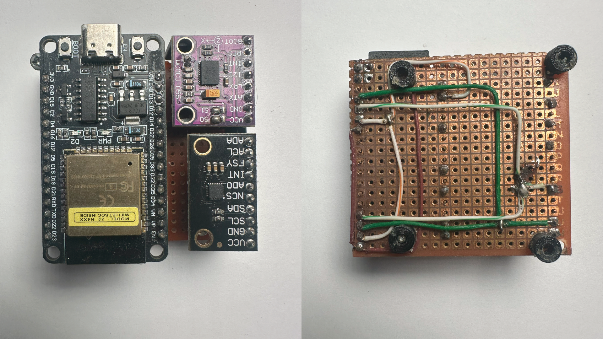
- ESP32-MCU 2 (Sensor Fusion Unit)
- Interfaces with two separate IMU sensors: the BNO055 and either LSM9DS1 or ICM20948.
- Performs real-time orientation estimation using:
- BNO055’s built-in NXP fusion filter, and
- Madgwick AHRS algorithm running on raw IMU data.
- Publishes sensor data (acceleration, angular velocity, magnetic field, and orientation quaternion) to the Raspberry Pi via serial USB.
This split architecture allows concurrent, uninterrupted processing of motor control and sensor fusion without overloading a single microcontroller.
3.2 Sensor Suite
Due to limited availability of high-end IMUs in Bangladesh, a combination of sensors was used for redundancy and comparative accuracy:
- BNO055 (Bosch): All-in-one IMU with internal fusion and drift correction.
- LSM9DS1 / ICM20948: Raw 9-DOF data fused via Madgwick AHRS on ESP32.
- Quadrature Encoders: Mounted on both rear wheels to track displacement and velocity for odometry.
- Steering Angle Feedback: Modified the MG996R servo to tap into its built-in potentiometer and read its value to determine the current steering angle.
Sensor readings are timestamped and sent at high frequency over USB serial to the Raspberry Pi.

3.3 Data Interface
Data Sent from ESP32s to Raspberry Pi:
- Orientation quaternion (from both IMUs)
- 3-axis accelerometer, gyroscope, magnetometer
- Steering angle
- Wheel encoder tick counts
Data Received from Raspberry Pi:
- Steering angle command
- Motor acceleration / throttle command
This bi-directional communication allows ROS 2 nodes on the Raspberry Pi to maintain full observability of vehicle state and issue precise control inputs in real time.
3.4 Power Distribution
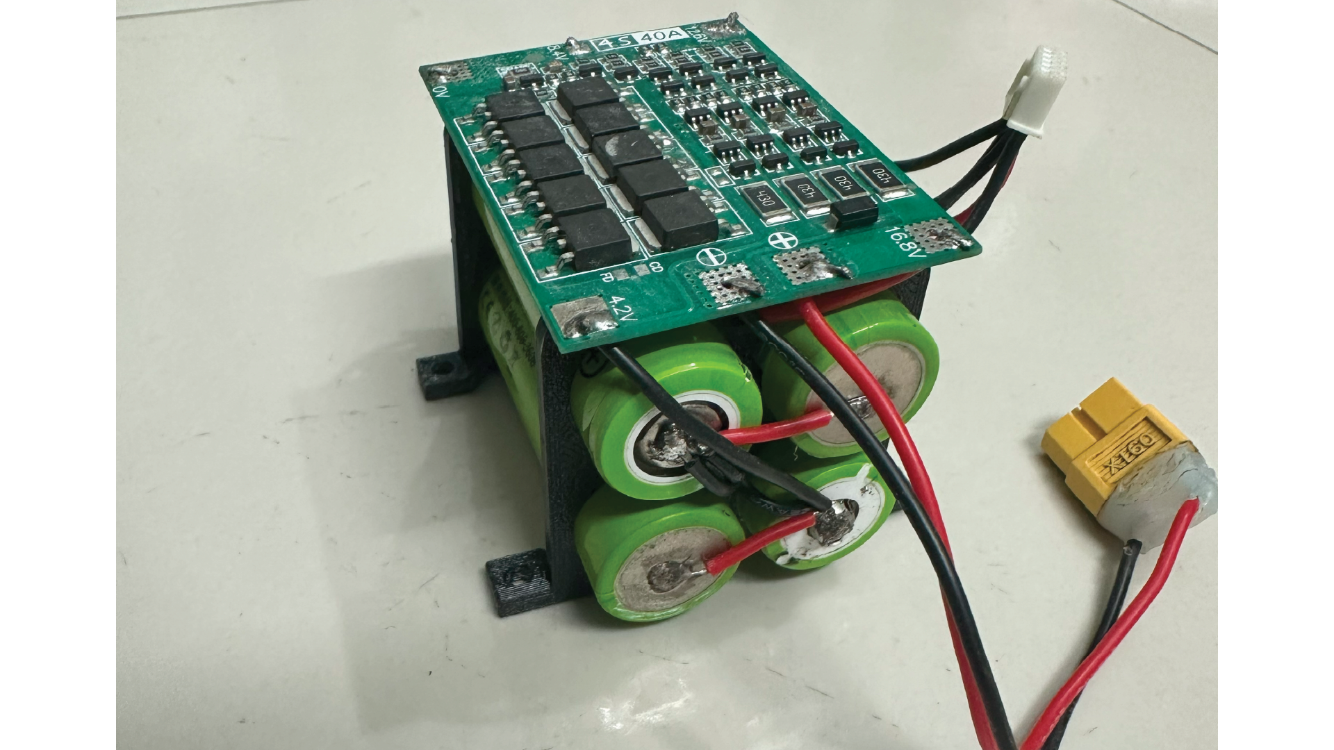
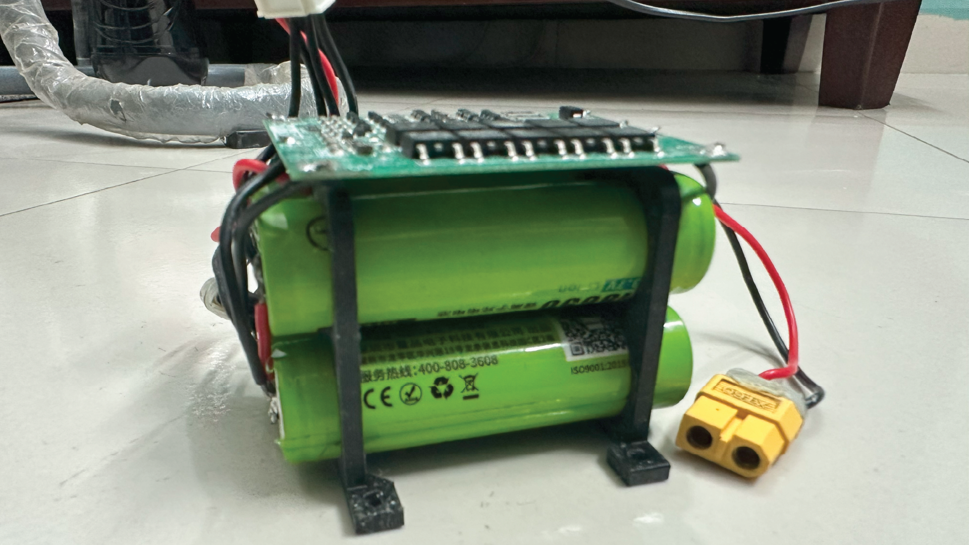
To meet the demands of both compute and actuation components, I designed a custom 4S Li-ion battery pack using four 18650 cells, wired in series. This provides a nominal voltage of 14.8V (up to 16.8V fully charged), sufficient to power the motor and Raspberry Pi simultaneously.
The battery pack includes:
- Cell balancer circuit for discharging and balance leads for cell-level monitoring and safe charging via a balance charger.
- XT60 connector for high-current output.
- Power switch for protection and safe power control.
To step down the voltage for specific subsystems, I used two separate buck converters:
- Buck Converter 1 – 5V Output: Powers the Raspberry Pi 5 with sufficient current headroom (~5A).
- Buck Converter 2 – 6V Output: Powers the DC motor, servo and other peripheral components. (~20A)
Each converter is rated above the expected load current and equipped with electrolytic capacitors for ripple suppression.
This power architecture ensures isolation, stability, and protection for both sensitive logic components and high-power actuators, while allowing safe recharging of the battery pack without
3.5 Motor Control
The drivetrain uses a dual-motor configuration, with each rear wheel independently driven by a high-torque DC motor. To control these motors, two BTS7960 H-Bridge motor drivers are used — one per motor — enabling differential-style drive control and enhanced torque performance.
Each BTS7960 is directly interfaced with ESP32-MCU 1, using dual PWM signals (IN1/IN2) to control both direction and speed. This setup allows for precise control of individual wheel speeds, providing a software-based differential and supporting accurate low-level motion control.
Key Features of BTS7960 Motor Driver:
- 43A peak current capacity per driver, suitable for high-load applications.
- 25 kHz PWM frequency for quiet, smooth motor operation.
- Independent control of each wheel for potential traction or torque vectoring experiments.
- Built-in protections:
- Overcurrent protection
- Overtemperature shutdown
- Undervoltage lockout and more!
3.6 Wiring and Circuit Layout
The custom PCBs includes headers and connectors for:
Control Circuit Board:
- Motor drivers (x2): PWM + direction signals to each BTS7960 driver.
- Steering servo: PWM control line.
- Wheel encoders: Quadrature inputs on interrupt-capable digital pins.
- Serial USB connection: For communication with Raspberry Pi 5.
- Buck converter input: For regulated 5V power to logic and
peripherals.
Sensor Circuit Board:
- 2x IMU modules: Connected via I2C.
.
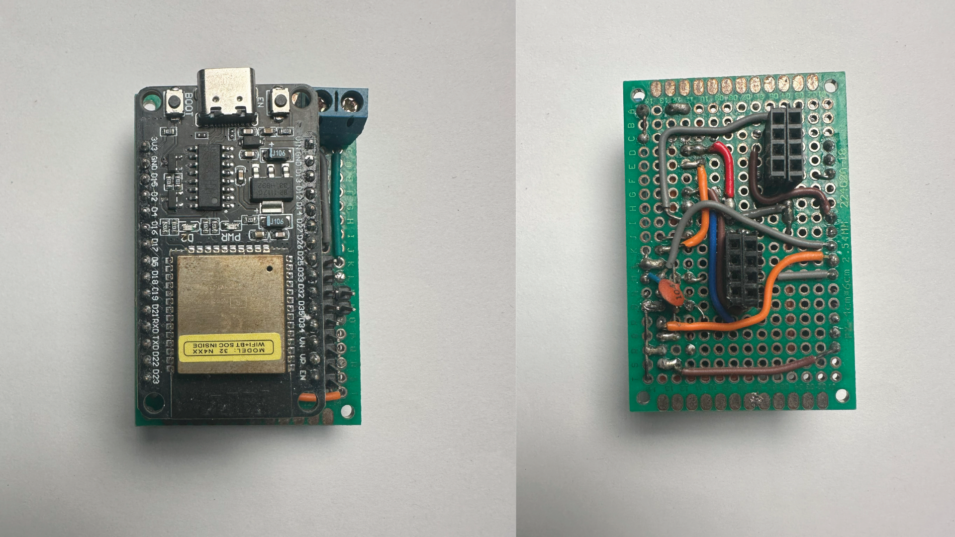
While these PCBs significantly reduce wire complexity, high-current and motor power lines are kept external and reinforced using thicker gauge wires and proper connectors for durability and thermal reliability.
By offloading all low-level I/O, timing-sensitive control, and sensor fusion to the ESP32s, this modular electronics architecture abstracts the hardware layer, allowing the Raspberry Pi 5 to focus solely on ROS 2-based perception, localization, and autonomous navigation.
4. Software Architecture for Autonomous Driving
The software stack for the autonomous Ackermann vehicle is built on ROS 2 Jazzy Jalisco, running on a Raspberry Pi 5 with Ubuntu Server. A separate remote PC running Ubuntu Desktop is used for teleoperation and real-time visualization in RViz over a local network.
4.1 Teleoperation and Command Interface
Initial testing was performed using keyboard teleoperation. A custom ROS 2 node was developed to convert /cmd_vel linear and angular velocity commands into Ackermann-style control inputs (linear speed and steering angle). These commands were transmitted via a serial connection to ESP32-MCU 1, which generated PWM signals to actuate the motor through an H-Bridge driver and control the servo for steering.
4.2 Sensor Data Publishing
ESP32-MCU 1 is responsible for sending wheel encoder tick counts and steering angle feedback to the Raspberry Pi via serial communication. A custom ROS 2 node named serial_multiplexer reads this stream and republishes the data on the /esp32/motor_serial topic.
Another node, odom_node, subscribes to /esp32/motor_serial, extracts the encoder ticks and steering angle, and calculates the vehicle’s linear velocity. It then applies the bicycle model using this velocity and steering angle to estimate the robot’s pose. The resulting position and orientation (as a quaternion) are published to the /wheel/odometry topic.
ESP32-MCU 2 handles inertial data by reading from two IMU modules — a BNO055 and either an LSM9DS1 or ICM20948 — depending on availability. The BNO055 provides orientation data via its internal NPX filter, while the second IMU uses a Madgwick filter for quaternion estimation. ROS 2 nodes publish the processed orientation as /imu/data_1 and /imu/data_2.
4.3 Sensor Fusion (EKF)
The robot employs the ROS 2 EKF (Extended Kalman Filter) node from robot_localization package to fuse data from both IMUs and the wheel odometry. The fused output is published on the /odometry/filtered topic, providing a high-accuracy estimate of the vehicle's pose for downstream navigation nodes.
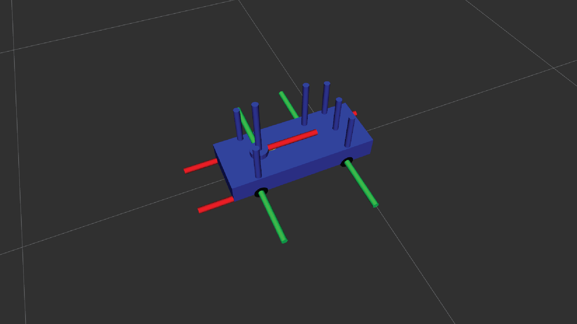
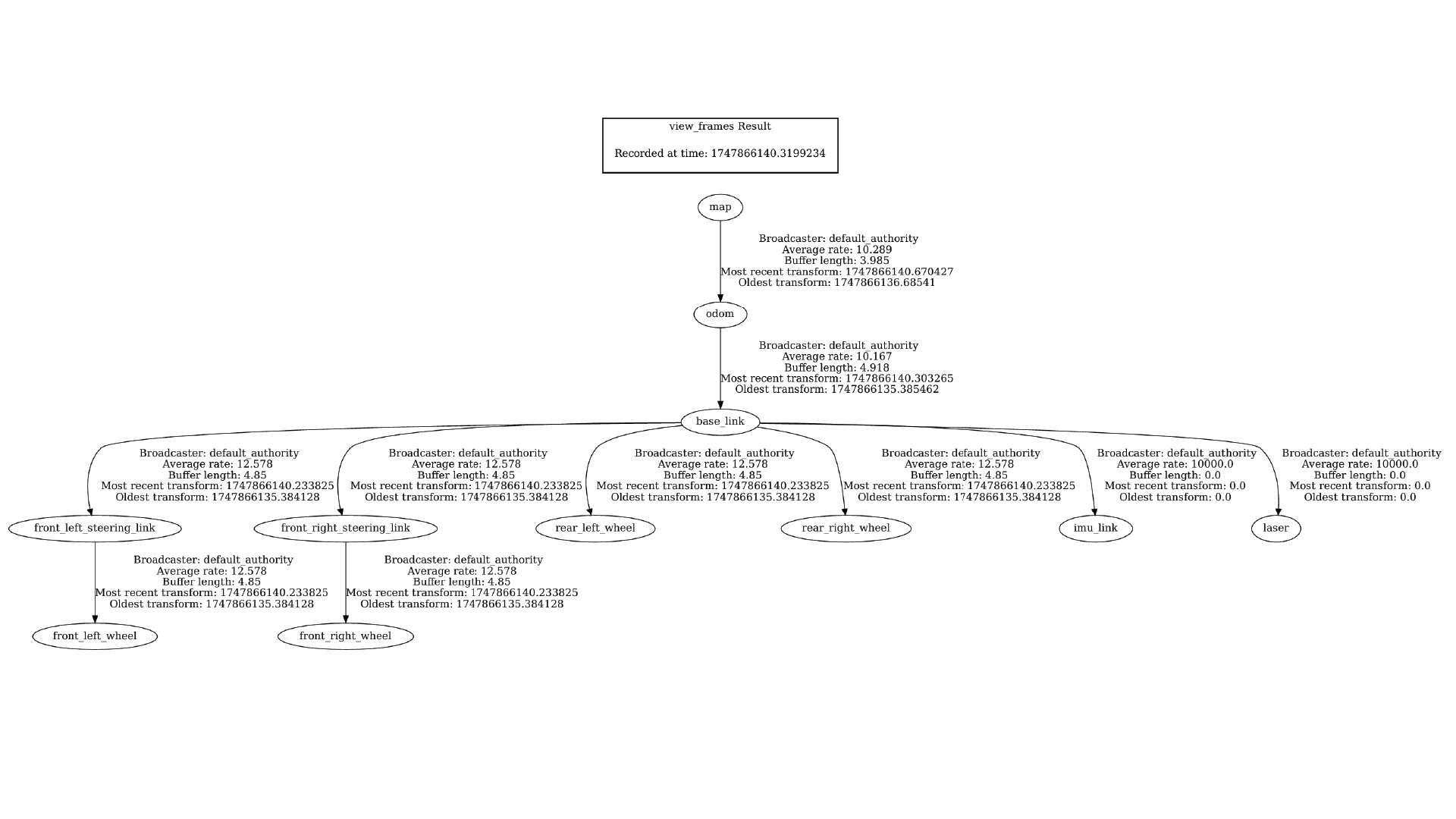
4.4 Robot Model and Joint Publishing
A detailed URDF (Unified Robot Description Format) model was created to accurately represent the vehicle’s physical structure, sensor placements, and articulation logic. This virtual model serves as the foundation for consistent visualization, transform broadcasting, and motion simulation in ROS 2.
URDF Components:
- Base link and chassis: Defines the robot’s main body and reference frame, acting as the root of the TF tree.
- Front wheels: Each front wheel uses two joints:
- A revolute joint for steering around the Z-axis (limited to a set range based on mechanical limits).
- A continuous joint for wheel rotation around the Y-axis.
- Rear wheels: Use a single continuous joint each, enabling free rotation without steering.
- Sensors: All IMUs, encoders, and the LiDAR are positioned according to ROS coordinate conventions, with +X forward, +Z upward, and +Y to the left, ensuring proper frame alignment across the system.
Joint State and Transform Publishing:
- A custom ROS 2 node subscribes to the
/esp32/motor_serialtopic, reads wheel encoder ticks and steering feedback, computes the current joint positions, and publishes them in real-time. joint_state_publisherandrobot_state_publisherare used to broadcast joint positions and derived transforms dynamically.- The system also uses static transform publishers to define fixed relationships between:
- The base link and sensor frames (e.g., IMU, LIDAR).
- The chassis and wheel mounting points.
These static transforms are essential for maintaining a coherent and complete TF tree, allowing all sensor data and motion to be understood relative to a consistent reference.
4.5 Visualization and Development Workflow
The development and debugging process was streamlined through a dual-system architecture:
- Raspberry Pi 5: Handles ROS 2 nodes for:
- Sensor communication
- Odometry computation
- EKF fusion
- LIDAR data publishing
- Remote PC: Used for:
- RViz visualization
- Keyboard teleoperation
- Monitoring
/odom,/imu/data, and/scan
All systems are interconnected over a local Wi-Fi network, enabling seamless communication while offloading compute-heavy tasks from the Pi.
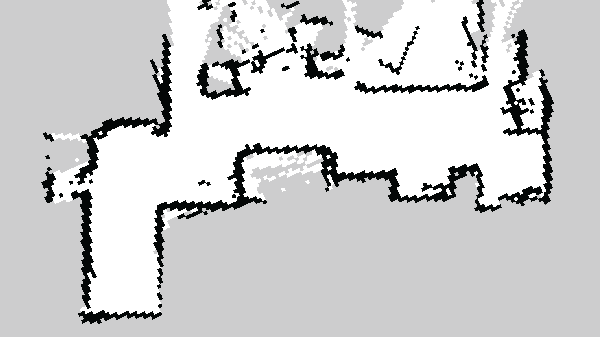
5. Mapping and Navigation with SLAM Toolbox and Nav2
Before enabling autonomous navigation, a 2D occupancy grid map of the environment (indoor room) was generated using SLAM Toolbox in online_async mode. This was done with a custom launch file and tuned .yaml parameter file tailored to the robot’s sensor configuration and dynamics. The resulting map was saved and used by the map_server node during navigation runs.
5.1 Localization
Localization was handled using the AMCL (Adaptive Monte Carlo Localization) node. Key configurations include:
- Laser model type:
likelihood_field - Robot model type:
OmniMotionModel(used for its smoother handling of Ackermann-like motion)
AMCL used laser scan data and the static map published by map_server to continuously estimate the robot’s pose on the map.
5.2 Path Planning
Global planning was performed using the Smac Planner plugin in hybrid-A* mode. Configuration highlights:
- Planner type:
SmacHybridA* - Motion model:
DUBIN(used for non-holonomic constraints) - Costmap layers:
static_layer,inflation_layeron global costmap
This setup enabled generation of smooth, feasible paths suitable for Ackermann steering vehicles.
5.3 Local Control
Two controller plugins were tested and configured:
- Model Predictive Path Integral (MPPI) Controller:
Used with:SimpleProgressCheckerandSimpleGoalChecker- Motion model: Ackermann
- Critics used:
CostCritic,PathAlignCritic,PathFollowCritic,PathAngleCritic,PreferForwardCritic
On the Raspberry Pi 5, MPPI performed adequately at ~10 Hz without lag.
- Regulated Pure Pursuit (RPP) Controller:
Also used with:SimpleProgressCheckerandSimpleGoalChecker
RPP performed significantly better on the Pi, capable of running at up to 40 Hz. This made it the preferred controller for real-time navigation on embedded hardware.
Both controllers operated on the local costmap with the following layers:static_layer, obstacle_layer, and inflation_layer, ensuring real-time collision avoidance and smooth path following.
5.4 Behavior Tree
The Nav2 navigation logic was governed by a modular Behavior Tree (BT), utilizing:
NavigateToPoseNavigatorNavigateThroughPosesNavigator
These BT nodes managed goal execution, feedback handling, and transitions across planning and control phases.
This setup allowed the robot to fully autonomously navigate through indoor environments with accurate localization, smooth planning, and responsive control — all running directly on a Raspberry Pi 5.
The RQT graph above illustrates the ROS 2 node architecture and topic communication flow of the autonomous vehicle during operation, providing a clear overview of how different subsystems interact.
6. Conclusion
This project successfully demonstrates the design, fabrication, and deployment of a 1/10 scale Ackermann-steering autonomous ground vehicle, built entirely with custom 3D-printed mechanical components, precision electronics, and a ROS 2-based software stack. By splitting responsibilities across dual ESP32 microcontrollers and a Raspberry Pi 5, the system achieved efficient real-time sensor fusion, low-level motor control, and high-level autonomy.
The integration of SLAM Toolbox for mapping and Nav2 for planning and control enabled robust autonomous navigation in indoor environments. Key design choices—such as using a rack-and-pinion steering system with bearing-supported uprights, modular circuit boards for clean wiring, and support for multiple IMUs—ensured mechanical accuracy and sensing reliability, which were critical for dependable odometry and localization.
Overall, this platform serves as a scalable and modular testbed for experimenting with advanced navigation techniques, motion planning algorithms, and real-world robotic system integration using ROS 2. Future extensions may include outdoor mapping, GPS integration, and vision-based perception systems.