ROS 2-Based Teleoperated Ackermann Vehicle with Custom Mechanical and Electronics Design

Introduction
This project began with the goal of transforming a low-cost RC car into a fully functional 1/10 scale autonomous ground vehicle with Ackermann steering, intended to run navigation algorithms using ROS 2. The aim was to design a complete small-scale robotics platform by building all key subsystems — mechanical, electrical, and software — from scratch.
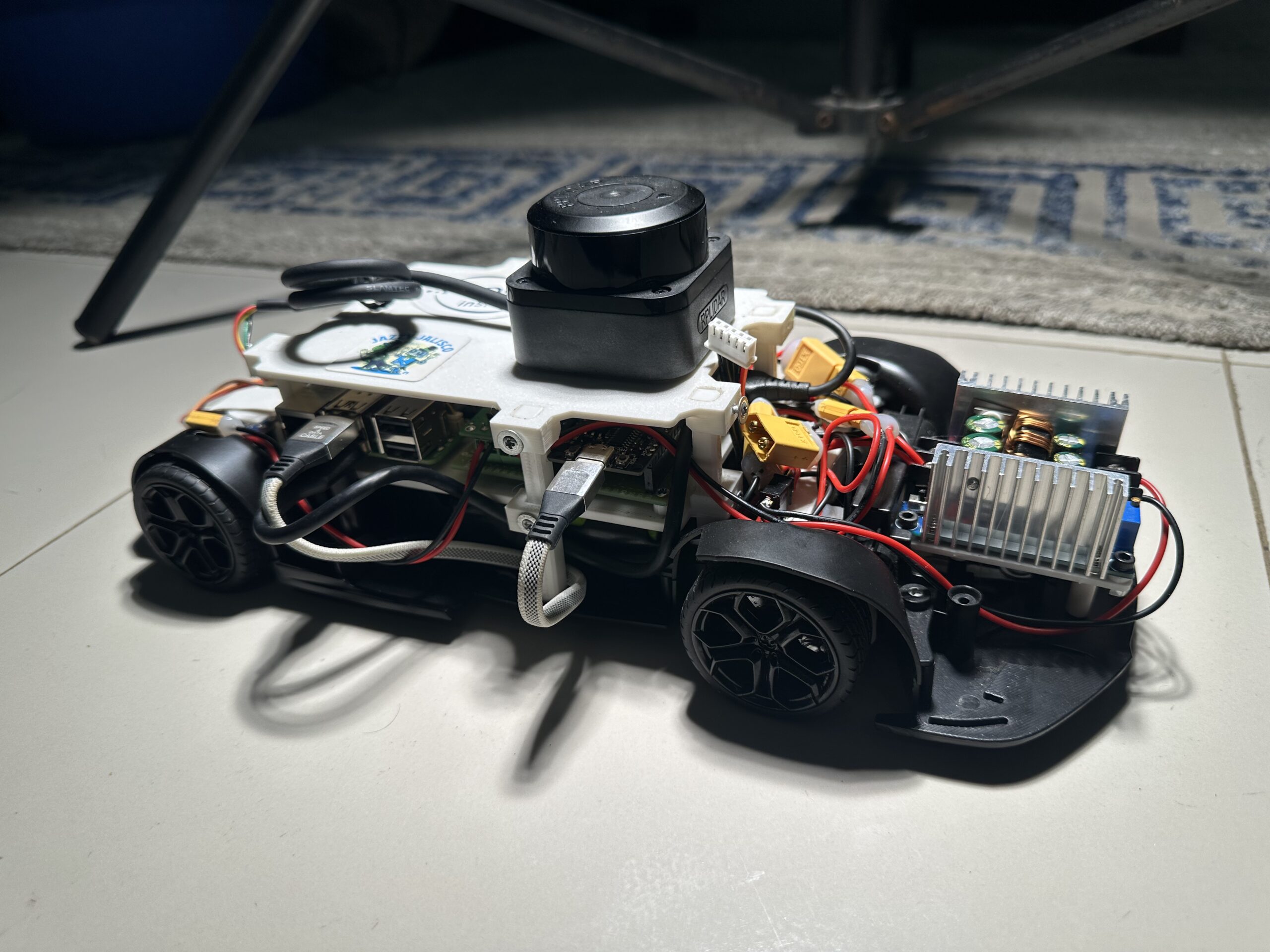
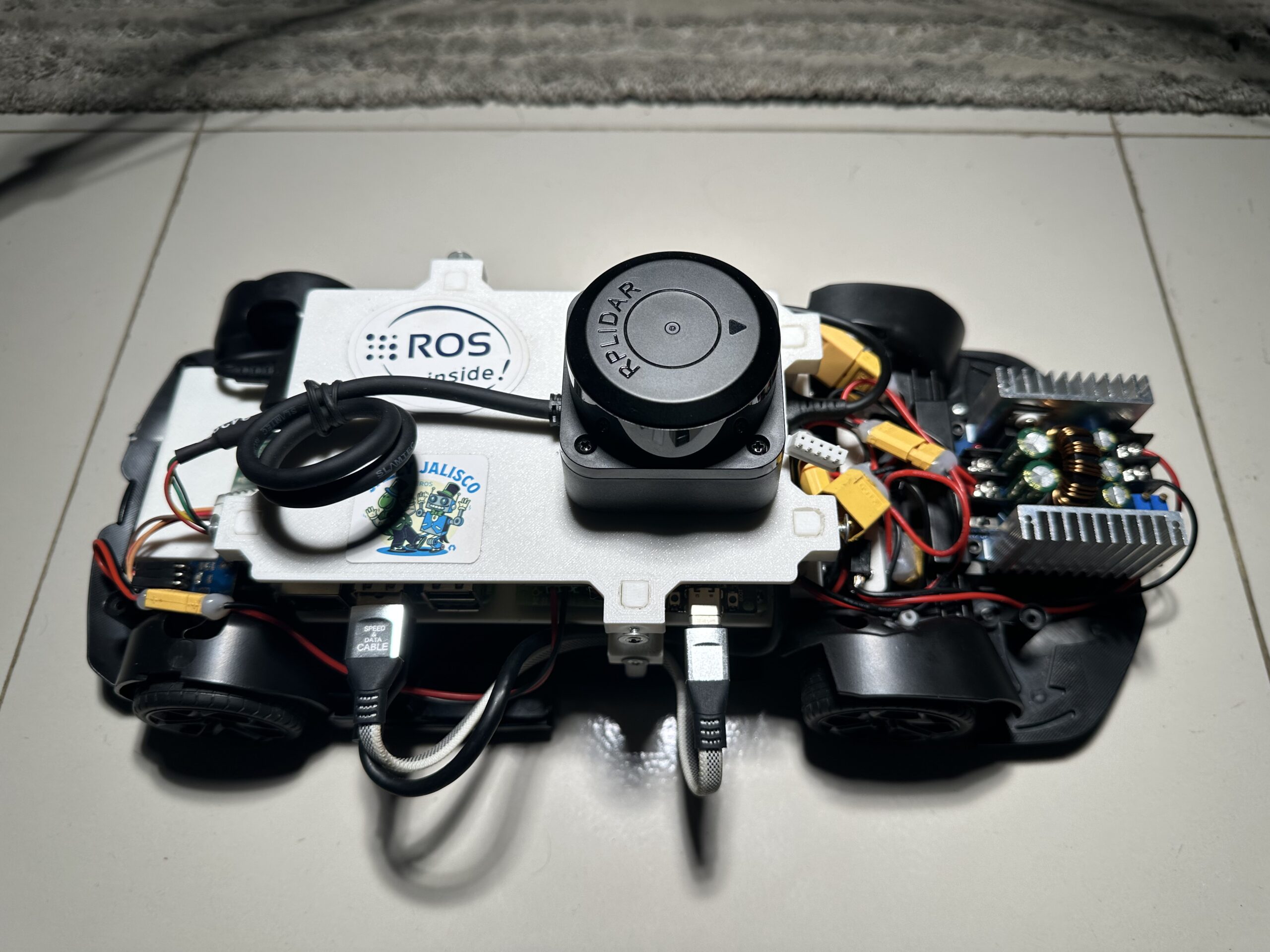
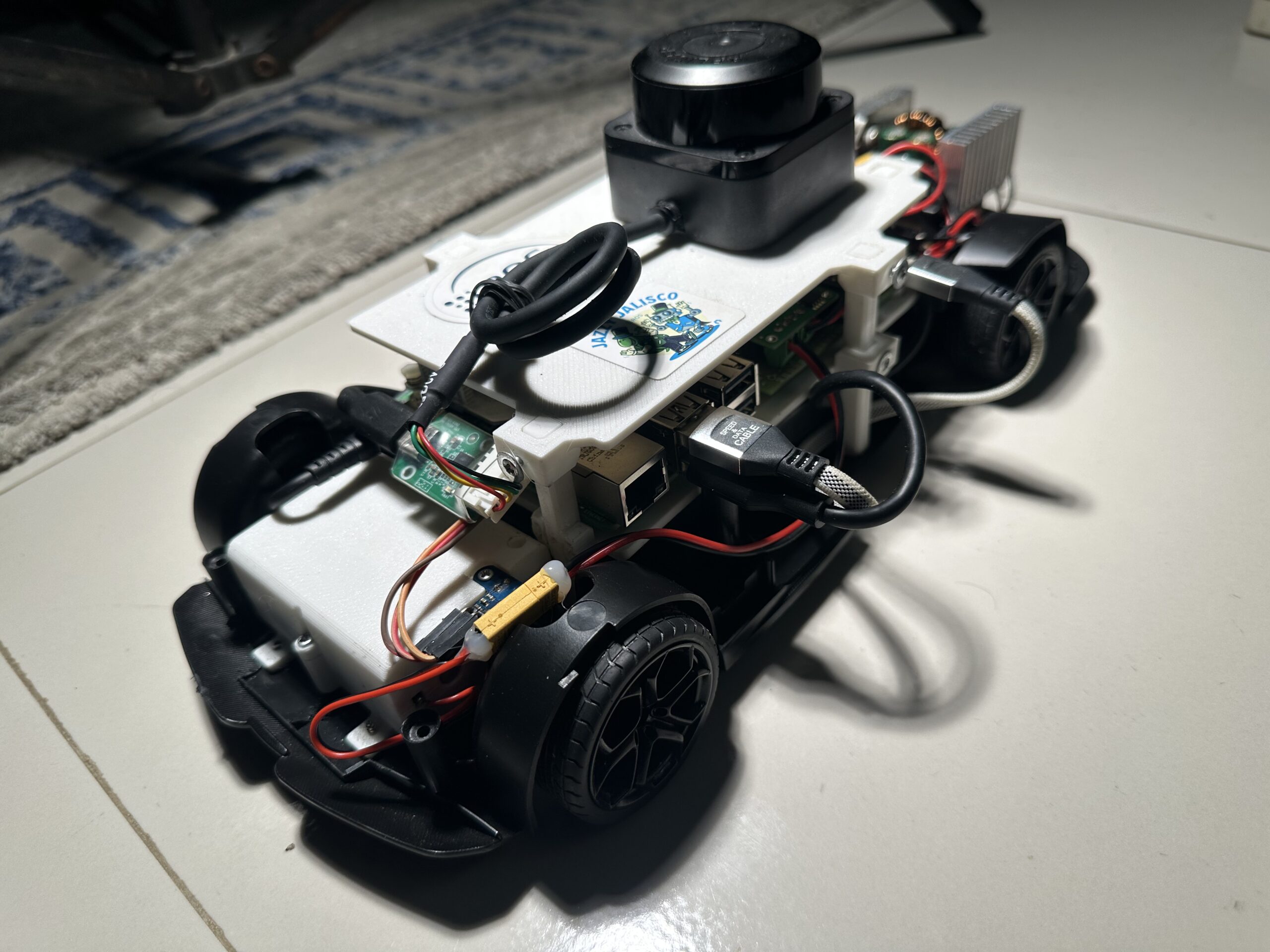
Starting with a toy-grade RC car chassis, I re-engineered the vehicle to support autonomous operation. This included replacing the original steering and drive systems with high-precision actuators, designing custom gear trains and 3D-printed housings, and integrating essential sensors such as a 9-DOF IMU, wheel encoder, and RPLIDAR C1 for localization and mapping.
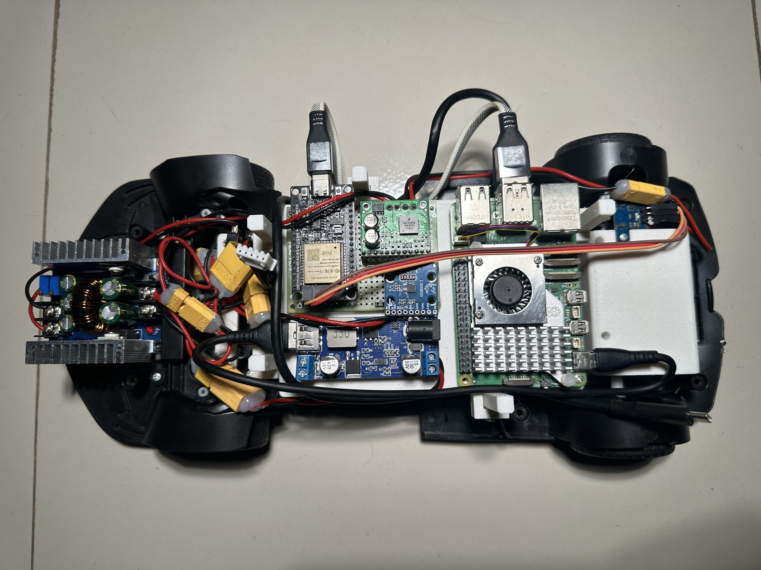
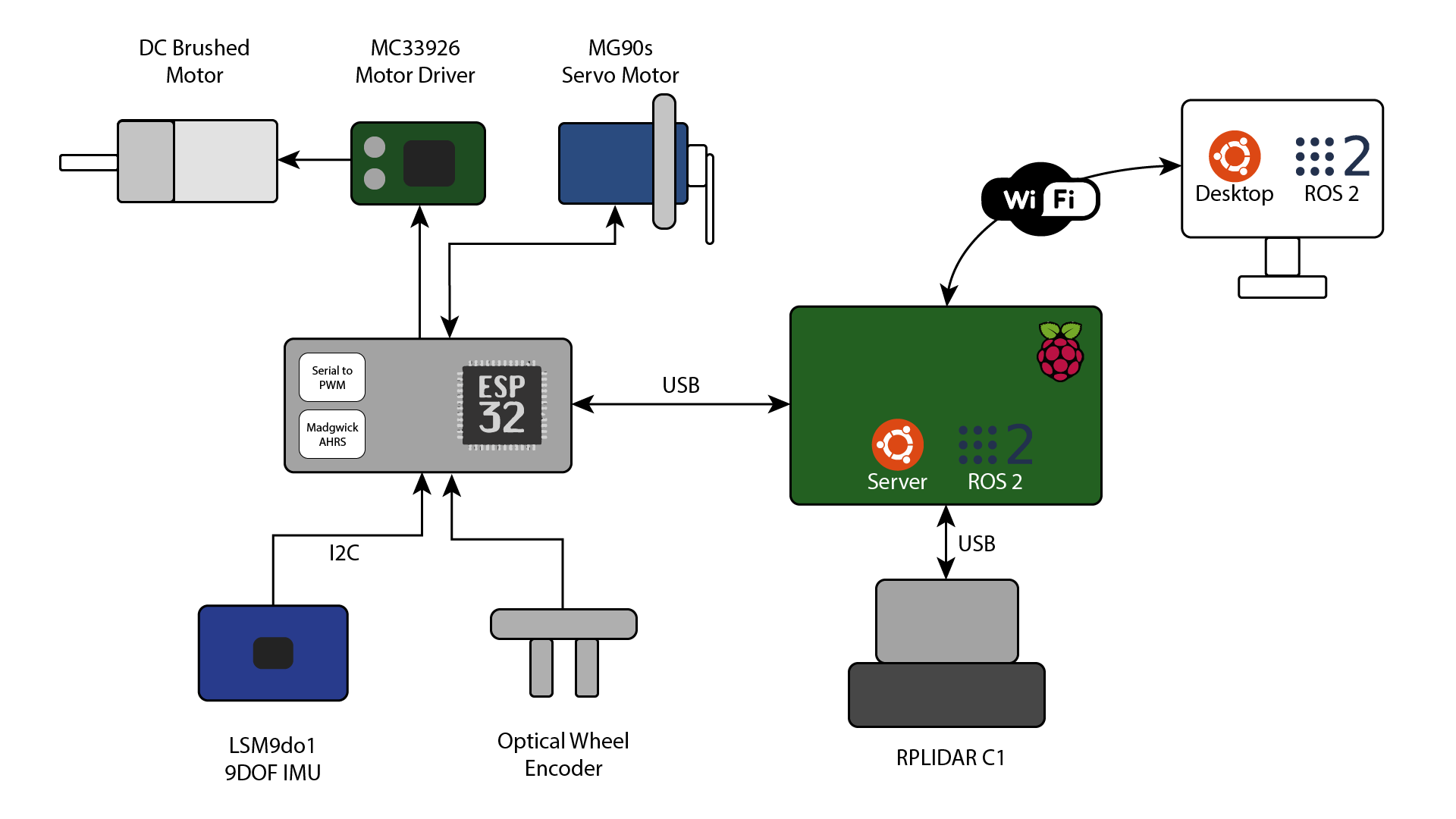
On the electronics side, I designed and fabricated a custom PCB housing an ESP32 microcontroller, the LSM9DS1 IMU, and an MC33926 motor driver, with connectors for power, encoders, and servo control. The ESP32 communicated with a Raspberry Pi 5 over serial USB, acting as the real-time bridge between low-level hardware and the ROS 2 ecosystem.
Although the system architecture was designed to support full autonomy via SLAM (GMapping) and the Nav2 stack, the project was ultimately halted after implementing manual teleoperation due to insufficient mechanical accuracy in the steering and drivetrain joints — which made reliable odometry and localization unfeasible.
This article documents the completed portions of the build — mechanical modifications, electronics integration, sensor communication, and ROS 2-based teleoperation — as a reference for anyone developing their own ground vehicle platforms from the ground up
Part 1: Mechanical Design and Hardware Modifications
The foundation of this project began with a low-cost RC car that served primarily as a rolling chassis. Its original steering and drivetrain components were unsuitable for precise autonomous control, so I opted to strip down and replace key mechanical parts to enable reliable, accurate vehicle behavior.
Steering System Upgrade
The stock steering system used a basic brushed motor with a simple mechanical linkage, lacking the precision and feedback required for autonomous navigation. I replaced it with a high-torque digital servo motor, mounted securely using a custom-designed bracket to directly drive the front wheels with consistent and predictable Ackermann geometry. This upgrade significantly improved the control authority and made steering angle feedback possible.
Drive System Redesign
The original brushed motor lacked sufficient torque for controlled movement at low speeds, especially when performing slow maneuvers required by navigation algorithms. To address this:
- I selected a DC gear motor with a higher torque output.
- Designed and 3D-printed a custom motor mount that fit the RC car’s internal frame.
- Created a custom gear train to match the required speed-to-torque ratio, ensuring smooth low-speed movement.
Encoder Integration
Accurate odometry requires precise measurement of wheel rotations. To achieve this, I:
- Added a rotary encoder to the drive shaft.
- Designed an encoder wheel.
- Designed a 3D-printed housing to mount the encoder securely while maintaining alignment with the shaft.
Part 2: Electronics Design and PCB Integration
To ensure reliable communication between sensors, actuators, and the high-level control stack, I designed and fabricated a custom PCB tailored specifically for the needs of the 1/10 Ackermann vehicle. This board serves as the central hub for low-level control and sensor fusion, enabling real-time feedback and command execution.
ESP32-Based Control Board
At the core of the electronics system is the ESP32 microcontroller, chosen for its dual-core performance, low-latency GPIO access, and built-in WiFi and serial communication capabilities. The ESP32 handles:
- Real-time data acquisition from sensors.
- Execution of sensor fusion (orientation estimation via Madgwick filter).
- Control signal output to the motor driver and steering servo.
- Serial communication with the Raspberry Pi 5 via USB.
Sensor Suite and Integration
The control board integrates several key sensors critical to autonomous operation:
- LSM9DS1 9-DOF IMU: Provides 3-axis accelerometer, gyroscope, and magnetometer data.
- Quadrature Wheel Encoder: Measures wheel rotations for accurate odometry.
- Steering Angle Feedback: Captured either from a servo with feedback or a potentiometer-based setup.
Sensor data is sampled at high frequency, fused using the Madgwick AHRS algorithm on the ESP32, and packaged into serial messages for the onboard computer.
Data Sent to Raspberry Pi:
- 3-axis accelerometer
- 3-axis gyroscope
- 3-axis magnetometer
- Orientation quaternion
- Steering angle
- Encoder tick count
Data Received from Raspberry Pi:
- Target steering angle
- Acceleration (or throttle) command
This bidirectional data flow ensures that the Raspberry Pi, running ROS 2, maintains a high-fidelity view of the robot’s state and can issue accurate motion commands.
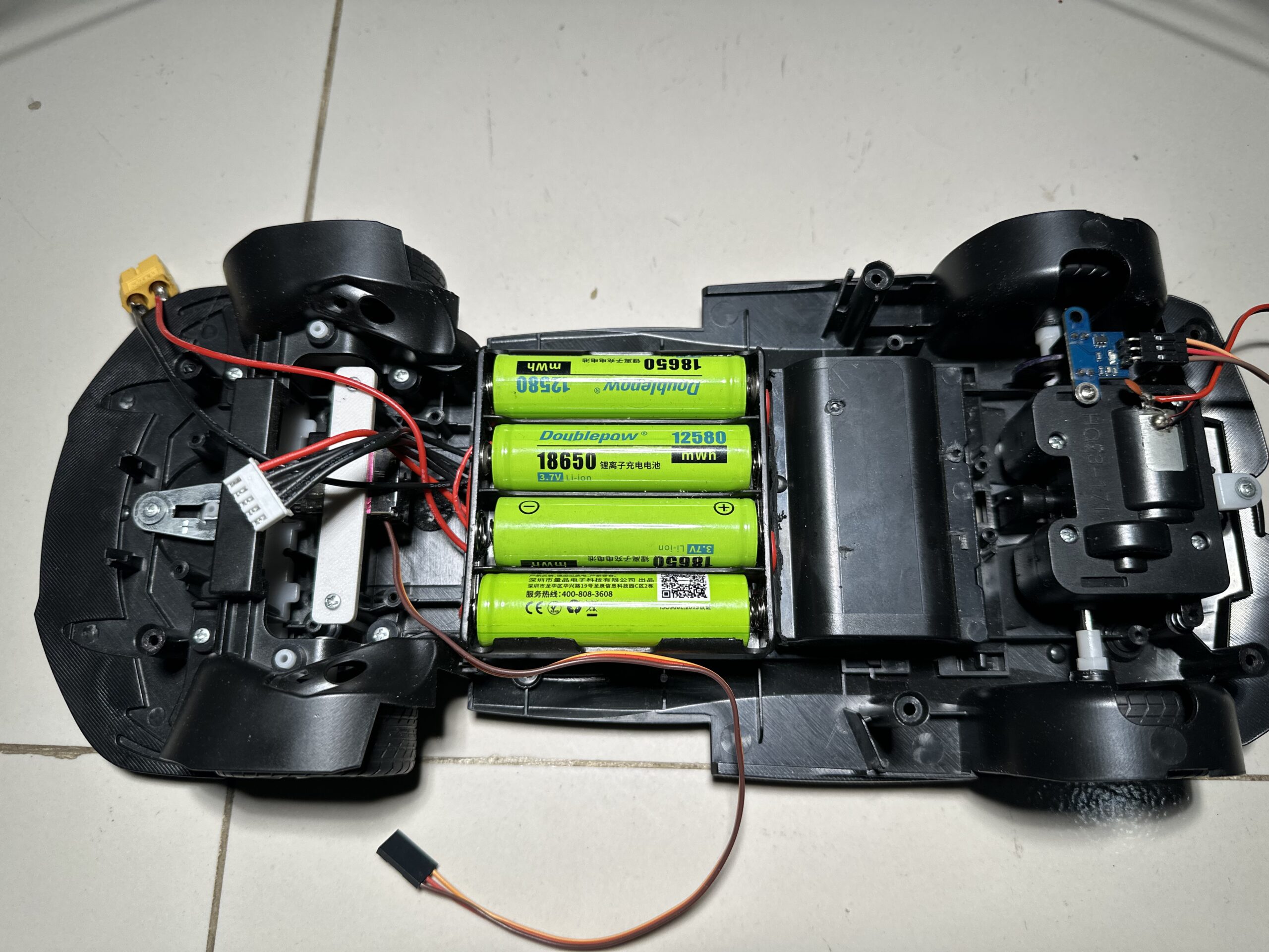
Power Distribution
To meet the demands of both compute and actuation components, I designed a custom 4S Li-ion battery pack using four 18650 cells, wired in series. This provides a nominal voltage of 14.8V (up to 16.8V fully charged), sufficient to power the motor and Raspberry Pi simultaneously.
The battery pack includes:
- Balance leads for cell-level monitoring and safe charging via a balance charger.
- XT60 connector for high-current output.
- Power switch for protection and safe power control.
To step down the voltage for specific subsystems, I used two separate buck converters:
- Buck Converter 1 – 5V Output: Powers the Raspberry Pi 5 with sufficient current headroom (~3A).
- Buck Converter 2 – 6V Output: Powers the DC motor, servo and other peripheral components.
Each converter is rated above the expected load current and equipped with electrolytic capacitors for ripple suppression.
This power architecture ensures isolation, stability, and protection for both sensitive logic components and high-power actuators, while allowing safe recharging of the battery pack without disassembly.
Motor Control
Motor driving is handled via the MC33926 H-Bridge motor driver, which is controlled directly by the ESP32 using PWM for speed and direction control. The driver supports current feedback and thermal protection, making it suitable for sustained operation under load.
Wiring and PCB Layout
The custom PCB includes headers and connectors for:
- IMU (via I2C)
- Motor driver (PWM and direction)
- Servo (PWM)
- Encoder inputs (interrupt-capable digital lines)
- Serial USB to Pi
- Buck converter power inputs
While the wiring was kept minimal via PCB routing, external connections like power and motor wires were reinforced for durability.
This modular and custom-designed electronics layer abstracts all low-level hardware interactions, freeing the Raspberry Pi to focus solely on high-level logic, navigation, and ROS 2 integration.
Part 3: Software Architecture with ROS 2
The software stack for the autonomous Ackermann vehicle is built using ROS 2 Jazzy Jalisco, running on a Raspberry Pi 5. A separate remote PC is used for visualization in RViz and remote teleoperation. The architecture is modular, with custom ROS 2 nodes handling everything from low-level serial communication to high-level state estimation and navigation, forming a robust pipeline for future SLAM and Nav2 integration.
Teleoperation and Command Handling
Initial testing and control of the vehicle are performed using teleoperation via keyboard from the PC. The PC publishes geometry_msgs/Twist messages to the /cmd_vel topic over a Wi-Fi connection.
On the Pi, a custom ROS 2 node subscribes to /cmd_vel and converts the linear and angular velocity commands into:
- A steering angle command for the servo.
- A throttle (acceleration) command for the motor.
These are transmitted to the ESP32 microcontroller over serial USB, where the actual hardware actuation occurs.
Sensor Data Publishing
The ESP32 continuously sends fused orientation and sensor data to the Raspberry Pi. On the Pi, I run a ROS 2 node that parses this serial data and publishes the following topics:
- /imu/data: A sensor_msgs/Imu message with orientation as quaternion + raw accelerometer, gyro, and magnetometer readings.
- /odom: A nav_msgs/Odometry message computed from wheel encoder and steering angle inputs.
The RPLIDAR C1 is mounted at the front and connected directly to the Pi over USB. A ROS 2 driver node publishes /scan at 10 Hz, providing 2D range data for mapping and navigation.
All transform relationships are published using the robot_state_publisher, ensuring that each sensor's data is correctly aligned within the robot's coordinate space — critical for fusion and planning.
Odometry and EKF-Based State Estimation
To compute accurate odometry, I implemented a custom ROS 2 node that uses a bicycle kinematic model. This model receives:
Encoder ticks (to estimate distance traveled).
Steering angle (to determine turn radius).
Using these inputs, it calculates the vehicle’s pose and velocity, and publishes it to the /odom topic.
To improve localization accuracy, I configured the robot_localization package to run an Extended Kalman Filter (EKF) node. The EKF fuses:
- /odom: From encoder + steering angle via the bicycle model.
- /imu/data: From the ESP32's Madgwick-filtered orientation and angular velocities.
This fusion produces a drift-minimized and stable pose estimate, critical for mapping, path planning, and closed-loop control in future stages.
Robot Model (URDF)
A detailed URDF (Unified Robot Description Format) model was created to represent the vehicle's geometry and motion constraints. The model includes all physical dimensions and kinematic relationships, critical for accurate visualization and integration with ROS 2 tools.
Key features of the URDF:
- Base link and chassis: Defines the reference frame and center of mass.
- Wheel joints:Front wheels use two joints each:
- A revolute joint for steering around the vertical axis (z) — limited to a specific angle range.
- A continuous joint for wheel rotation around the horizontal axis (y).
- Rear wheels use only a continuous joint for rotation, with no steering.
- All joints and links are assigned proper visual, and collision properties to allow for realistic simulation and RViz rendering.
Frame definitions such as base_link, imu_link, odom, and laser_frame were set up to support both kinematic calculations and sensor alignment.
Visualization and Development Workflow
The development workflow uses a dual-system setup:
- Raspberry Pi 5: Runs ROS 2 nodes for sensor communication, odometry, EKF, and LIDAR.
- Remote PC: Handles:
- Teleoperation via keyboard.
- Visualization in RViz.
- Monitoring of /odom, /imu/data, and /scan.
All communication occurs over a local network, keeping the compute-heavy tasks on the Pi lightweight and responsive.
Upcoming Autonomous Stack
With the sensing and control framework in place, the next phase of development will include:
- SLAM with GMapping: To build an occupancy grid map from laser scans and EKF pose data.
- Nav2 (Navigation 2 stack): For global and local path planning, obstacle avoidance, and autonomous goal tracking.
The current system design ensures full compatibility with standard ROS 2 navigation tools, minimizing integration friction in future work.
Description
Engineered a 1/10 scale Ackermann steering robotic platform with full mechanical redesign (steering linkage, gearbox) and custom-designed electronic circuits and PCBs. Integrated multi-sensor inputs including RPLIDAR, a 9-DOF IMU (accelerometer, gyroscope, magnetometer), and wheel encoders for state estimation. Although originally designed for autonomous navigation using the ROS 2 Nav2 stack, the project was concluded after successful teleoperation due to mechanical limitations in odometry accuracy.